The Design Process
Objectives were for each of the engine derivatives with objective power and torque being contained within the limits of each of the standard TVR engines and driveline...
Initial studies of the alternative forced induction systems available, their costs, performance, pros and cons were assessed. Turbo charging was put aside reasonably quickly due to problems and costs involved in controlling heat within the engine bay, it was essential to generate a system meeting our power objectives, fitting in both the Griffith and Chimaera engine bays and under the existing bonnet lines. This is tall order when there is little space available. There is not much spare package space under the bonnet to accommodate the extra clearance between the hot turbo and other ancillary equipment, let alone the increased requirement for insulation to protect the GRP bonnet. The problem with turbochargers is they have to be fitted to the exhaust, this restricting the options for location. We soon decided Supercharging was the most viable and probably cost effective option.
Our goal was to offer ‘ Bolt on' Supercharger systems both to the standard range of engines, and to high performance units whereby engines would be modified by cross-bolting, reducing compression and upgrading internal components to meet the increased loading. The ECU and 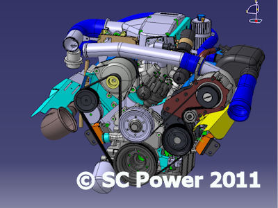 fuelling would also be changed to support the power demand.
The system had to be developed primarily for road/track usage, maintaining drive-ability when on the road and offering superlative power when on the track. We did not have the objective to develop the ‘most powerful engine', well not at that time anyway.
Further consideration was given to the choice of Supercharger from the available options, these being either fixed displacement superchargers of either screw or Roots types or the Centrifugal type that have similarities to turbocharger driven by belt rather than the engine exhaust gas. Fixed displacement Superchargers generate more torque and give increase performance lower down the engine speed range, the Centrifugal type being linear, generating power and torque progressively as the engine speed rises.
Historically there have been reported problems of fixed displacement units when fitted directly within the ‘V' of the block, with little header length poor air/fuel distribution to the cylinders can occur, resulting with a weak mix to one or more cylinders causing overheating detonation and component failure. There was also insufficient space to mount these systems remotely within the available package space without modification to the bonnet lines; they are more expensive and difficult to intercool.
The technology of Centrifugal Superchargers has come a long way, with efficiency, performance and of equal importance quietness. Systems now being incorporated into high production sports vehicles being produced by major OEM's.
A Rotrex supercharger was finally selected, due to compactness, high efficiency, low noise and reliability. The state of the art traction drive technology unit offered the greatest scope for installation. 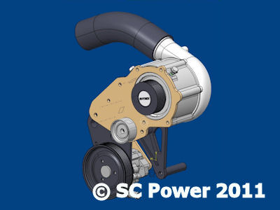
The following extract is taken from the Rotrex web site and gives an ‘in depth' overview of the method of drive and advantages.
Great speeds and low noise are just some of the advantages of traction drives over traditional gear transmissions. Traction drives transmit power through friction forces between its rolling elements. The Rotrex patented traction drive uses an elastic annulus with a small pre-span to secure contact between the roller planets and the sun shaft with a reasonable force. The patented "ramp effect" increases efficiency and reliability in the transmission by regulating the torque transfer capability on demand through self-adjusting planet geometry.
To enhance performance, the Rotrex traction drive uses a special traction fluid. These fluids are a new family of synthetic hydrocarbon oils and greases offering a series of unique performance advantages. Developed specially for its use in Rotrex superchargers, the SX100 momentarily increases viscosity under high surface pressure, enhancing the traction drive performance by securing the optimum friction between rolling elements while cooling and protecting the system.
This traction drive combined with the latest technology in centrifugal compression, characterized by high adiabatic efficiency and low noise, gives Rotrex superchargers an exceptional competitive edge over any other forced induction solution.
Before in depth studies could commence, the entire engine front body section and chassis had to be modelled into our Catia based 3 Dimensional systems. Modelling entailed careful measurement of every component, each point of data where a change of surface occurred being digitised into the computer to produce fully surfaced 3 dimensional models, every part able to be assembled and animated together to generate a complete engine that can be viewed from any position in ‘real time'. The same process was carried out for the Chassis, front suspension, cooling packages and the entire front end bodywork. When all areas were complete the engine could be viewed in its installed position with surrounding bodywork, chassis and other related systems. With the entire front end of the car simulated in the computer it allowed us simulate and view precise clearances between parts, also the relative movement of the engine when subjected to drive and braking forces encountered when in motion.
CAD model generation process took in excess of 6 months, but was absolutely necessary to generate the background from where the Supercharger system would evolve.
The Chimaera and Griffith have similar clearance between the bonnet and the engine, but the available package space forward of the engine is very restricted for the Griffith due to the bonnet closure path and the radiator location. The Griffith having the tighter package space had to dictate the design overall intake design to maximise common parts.
Design studies were evaluated of the method and system of mounting, each vehicle and engine variant with or without Power Steering, Air Conditioning, LHD or RHD and whether Intercooling would be necessary. All had to be considered, the final design able to accommodate every option, without the necessity to revise the bodywork or impede the service aspect of the vehicle. This was a tall order and a challenge, as there are 72 variants to be assessed by pre-study and subsequently in depth design evaluation.
The installation to the engine block and cylinder head had to minimise adverse forces to the mountings, these forces including inertia, vibration, compress ional, offset and rotational loads inducing bending and torsional moments. These aspects had to be assessed otherwise the durability of the system would be in question, resulting with possible part failure during the development phase and possibly during the early life of the product. This had to be avoided at all costs; the integrity of the cylinder head and block mountings being maintained, without 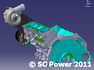 undue or excess stress.
Initial calculations of air flow requirement were assessed for each engine derivative to achieve the desired power rating, this ranging from 450 cu.ft./minute for the 4.0 litre engine with a 300bhp objective, to 600 cu.ft./minute for the 5.0 litre with the objective of achieving 400bhp, these objectives being dictated by the torque limitations of the clutch and Borg Warner T5 gearbox, the horsepower rise over the standard engine determining the supercharger selection and level of boost to achieve our goals. It soon became apparent the level of boost could be kept low, at around 5-6psi, this level of boost giving the benefit of a lower charge air temperature, minimizing the necessity to incorporate an Intercooler into the standard build.
Servicing was taken seriously to minimise costs, ensuring accurate alignment of the Supercharger and ancillary equipment pulleys. Should the system be removed and re-installed for servicing, alignment of the pulleys and belt had to be assured.
Materials for the mounting system were carefully evaluated to minimise weight, reduce the high frequency vibrations and minimise the centre of gravity offset to the relative to the engine mounting face, this in turn reducing excess stress and load transfer to the respective fixing points. To achieve this, the fabricated sandwich mounting system was chosen, as we could utilise carefully selected and differing materials for each part to achieve our goals. Cast bracket designs were also considered but discounted at this time as the required draft angles to facilitate manufacture resulted with a larger assembly, the mass would be significantly larger resulting with increased weight, this increasing the stress on the mountings. The cast bracket by virtue of its design, also limited our ability to use alternative materials to reduce stresses.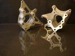
Other factors influencing the design were the positions of the base engine ancillary equipment, drive systems and exhaust run; the installation had to minimize the need to relocate the primary components. Advanced studies had identified potential positions to mount the Supercharger and equipment, the pros and cons of each location being considered and evaluated.
Staying with our philosophy to upgrade the base engine rather than to re-design, we decided together with TVR Power that the ECU, Air flow meter and Distributor and fuel injectors should remain, rather than incur the expense of changing to more sophisticated components. There are many views as to the capability of the 14cux ECU and air flow meter to cope with the required air flow to support these power ratings, all judgments being based upon the Naturally Aspirated engine, how these parts would perform when subjected to forced induction was to some degree predictable but unknown., the proof available, only when the engine had been subjected to Dyno evaluation.
The position currently occupied by the Power Steering Pump provided the best position to locate the Supercharger Power Steering pump. Power steering is optional, when not fitted it is replaced by an Idler in the same location.
In addition to the computer models of the engine, exhaust, chassis and surrounding bodywork, CAD models of the individual Supercharger units had to be generated, and we thank Rotrex for supplying us with detailed information to achieve this. When completed, all relative computer models were loaded into the system to determine the precise amount of space available, also to apply the envelope of required clearances to each component surface surrounding the installation, these clearances were determined by the local environment i.e. heat radiation from the exhaust. Measurements of engine movement were taken, with allowances being made for deviation when subjected to acceleration and braking forces. Clearances to the exhaust were set to minimise adverse heat transfer to the charger and drive system. The bonnet was also modelled with ‘Open and Closure' movement to see the clearances between the bonnet and system parts when the bonnet moved through its travel path. 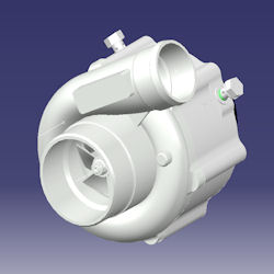
A package envelope was established, the charger being located within the defined space.
As previously determined, the Rotrex Supercharger fitted, the investigations continuing to relocate the Power Assisted Steering pump. Alternative positions of the PAS were reviewed, each position being assessed relative to clearances to the exhaust and other parts, the potential to achieve a good belt route with complying with our pulley overlap demands and satisfying the additional demands to facilitate servicing.
The design installation of any system considers all parts and routing simultaneously to generate an optimum solution, each part of jigsaw being moved finitely to reach the best overall design solution.
In total, the design process and development of the induction system took over 18 months and included in excess of 2000 hours of CAD time to perfect the solution.
The system complete build and testing could begin, the initial installation carried out in the TVR Power 4.0 litre Chimaera. The engine and driveline including clutch were kept to standard specification to ensure transfer loads were contained within the limitations of the system. Build was straightforward with installation clearances being exceptionally close to the theoretical CAD data. Minor wiring changes had to occur due to repositioning of the Air Flow Meter and the Stepper motor. After minor glitches to ensure everything was tight, secure and the new vacuum lines in place for the fuel regulator the engine fired up allowing the supercharger system to be run in on the Dyno. After several low speed runs, fuelling of the system was assessed and changes made to ensure good air/fuel ratios through the rpm range to the point of detonation, the engine being backed off to safe limits when this point was known. The car completed in excess of 40 Dyno runs over a relatively short period, each time tweaks being made to refine the engine output and ensure durability. The results were good, very very good, enough to make Dom ask whether he had installed a 5.0 litre engine instead of the 4.0 litre by 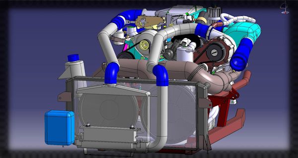 mistake, after all they do look identical.
For the past 10 months the car has undergone extensive testing and evaluation by professional drivers, the general public apart from our staff though the hottest of summers, track driving at home and abroad and being taken on holiday through the Alps. The car has behaved impeccably during this development phase and is a credit to the efforts and time given by our and TVR Power staff.
The results have been close to our prediction both of boost and intake temperatures, this minimising the need for an intercooler except on higher performance engines. With boost around 5+ psi and the pressurised air temperature rising about 45 degrees over ambient our performance objectives have been bettered without major change to the engine.